1. Introduction
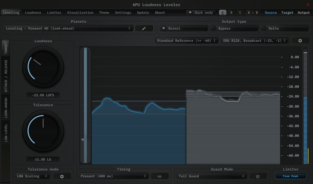
APU Loudness Leveler is a loudness leveling plug-in released by APU Software, LLC. This plug-in is designed to automatically maintain a target loudness level, with configurable tolerance, optional secondary target switching, guard modes, and sidechain control. Here you can read about the different features and parameters available with the plug-in.
2. Parameters
This software supports a variety of parameters, most of which can be adjusted in real-time. This section provides an overview of each parameter, with each subsection detailing the parameters for the associated tab in the user interface. From within the user interface, you can also hover the mouse over a slider, combo-box, or checkbox to see a popup description of the parameter.
2.1. Leveling
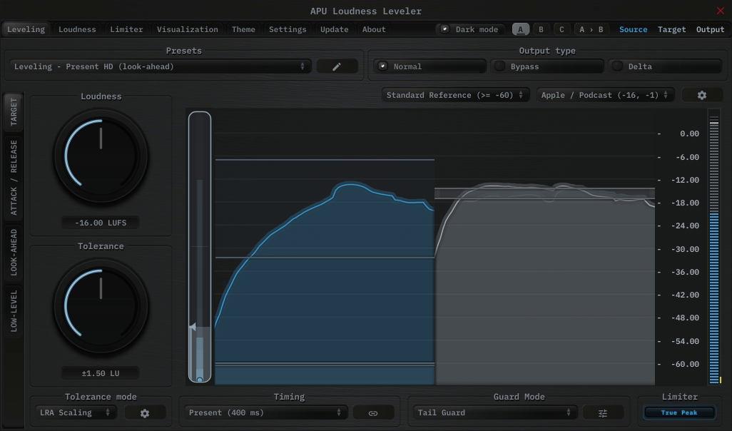
The leveling tab contains configuration and visualization for loudness leveling. This section details each of the individual parameters and components.
2.1.1. Presets
Loudness Leveler’s presets combo-box contains a collection of basic presets, one for each combination of timing mode style and latency configuration. Focus and Present presets use momentary loudness, Deep presets use short-term loudness, and Traditional presets use RMS.
See timing mode and look-ahead for an understanding of how the leveler derives its loudness window and delay behavior.
The preset browser includes user-scope load options for ordinary preset changes. Reset on preset load runs a filtered parameter reset before the preset is applied. Load preset visuals controls whether the preset can change the hinted theme and visualization settings. Full Reset always restores all default parameter values, regardless of these options. Load preset ranges protects target loudness, target tolerance, secondary loudness, and secondary tolerance. When disabled, those target zone values are skipped during both the pre-load reset and the preset load. You can switch between loading dark or light themes through the dark mode parameter.
Currently, the following presets are available (“Full Reset” restores all default parameter values):
- Full Reset
- Leveling - Tight (look-ahead)
- Leveling - Tight HD (look-ahead)
- Leveling - Focus (look-ahead)
- Leveling - Focus HD (look-ahead)
- Leveling - Present (look-ahead)
- Leveling - Present HD (look-ahead)
- Leveling - Deep (look-ahead)
- Leveling - Deep HD (look-ahead)
- Leveling - Traditional (look-ahead)
- Leveling - Tight (low-latency)
- Leveling - Tight HD (low-latency)
- Leveling - Focus (low-latency)
- Leveling - Focus HD (low-latency)
- Leveling - Present (low-latency)
- Leveling - Present HD (low-latency)
- Leveling - Deep (low-latency)
- Leveling - Deep HD (low-latency)
- Leveling - Traditional (low-latency)
- Narration - ACX Chapter
- Mastering - Spotify Reference (Stereo)
- Mastering - SoundCloud Reference (Stereo)
- Mastering - Tidal Reference (Stereo)
- Mastering - YouTube Reference (Stereo)
- Mastering - Amazon Music Reference (Stereo)
- Mastering - Deezer Reference (Stereo)
- Mastering - Apple Music Reference (Stereo)
- Creator - Social Media Short Form (Stereo)
- Narration - Podcast Episode (Stereo)
- Narration - Podcast Episode (Mono)
- Broadcast - EBU R 128 Programme
- Broadcast - ATSC A/85 Short Form
2.1.2. Output type
The output type options allows you to configure which type of samples to output.
- Default output type corresponds to Loudness Leveler’s output
- Bypass output type corresponds to Loudness Leveler’s source
- Delta output type corresponds to Loudness Leveler’s output minus source
Output gain and dry/wet are bypassed for Delta output type
2.1.3. Visualization
The visualization component displays a continuously evolving real-time view of your source, target, and output loudness over time. There are currently two main types of visualizations: history and histogram. History displays a rolling window of the most recent history of loudness samples. Histogram divides this history up into buckets and displays the relative proportion of each bucket in real-time.
You can hover the mouse over a bucket to see the loudness range the bucket corresponds to.
The visualization component also displays the active target zone, allowing you to see how closely the signal tracks the desired loudness zone. This normally uses target loudness and target tolerance, but the target-switching sidechain and low-level modes use secondary loudness and secondary tolerance instead. Detailed visualization settings can be adjusted from the visualization tab, with some features also available by right clicking on the visualization component.
You can double-click the visualization component to resize and hide everything else.
2.1.4. Raster type
The raster type parameter allows you to specify the type of raster visualization. You can select between history and histogram views, with either loudness or delta values. Loudness values match the active measurement implied by timing mode and channel link, while delta values take the difference between source and target or output loudness.
Delta view is useful for determining how much loudness is being changed, and how much residual there is between target and output loudness.
You can also visualize target vs output residual via breath residual option.
2.1.5. Vibe check
The vibe check toggle allows you to enable or disable the vibe check feature. When enabled, the pre-limiter gain target continuously cycles between attack and release phases across a fixed positive/negative correction range.
During this sweep, the current attack/release settings determine how quickly the gain moves. This acts like a magnifying glass for tuning ballistics because small timing changes become much easier to hear, while the built-in limiter still clamps afterward when enabled.
2.1.6. Timing mode
The timing mode combo-box allows you to choose a ballistics preset that determines how Loudness Leveler responds to changes in source loudness. Timing mode also determines which loudness window the leveler uses internally.
- Tight uses a 25ms momentary loudness window.
- Focus uses a 100ms momentary loudness window.
- Present uses a 400ms momentary loudness window.
- Deep uses a 3s short-term loudness window.
- Traditional uses a 300ms RMS window.
2.1.7. Low-latency timing
The low-latency timing toggle switches the selected timing mode from delayed look-ahead to predictive response with no added delay.
Low-latency timing does not use a true delayed look-ahead buffer. Instead, when look-ahead mode is not OFF, it uses the configured look-ahead amount as a stochastic prediction horizon.
2.1.8. Compensation mode
The compensation mode combo-box chooses how Loudness Leveler measures the output signal while compensation learning is active.
- Average learns a single correction from the mean output loudness over the current render, using the measurement implied by timing mode and channel link.
- Integrated learns a single correction from integrated output loudness over the current render.
Both modes learn toward the primary target loudness. Integrated compensation compares this target value against Integrated LUFS, including when the timing mode uses RMS. Both modes are intended for learn-then-lock workflows: start learning on a representative pass, then lock the learned correction for normal playback or export.
Compensation adds a stored global offset on top of the normal rolling leveler behavior. It does not replace target tolerance or the existing learn/tolerance path.
2.1.9. Compensation gain
The compensation gain field stores an additional global gain offset in dB that is added to Loudness Leveler’s normal leveler result.
When compensation learning is off, you can edit this value directly for manual trim. When learning is on, the field shows the live learned value, but the stored parameter is only updated once you lock learning.
Use the compensation action button to quickly learn, lock, or reset this value without leaving the main leveling workflow.
2.1.10. Compensation action
The compensation action button changes behavior based on the current compensation state.
- Learn starts measuring the selected compensation mode and updates a live learned correction.
- Lock stops learning and commits the current learned correction into compensation gain.
- Reset clears the stored compensation gain back to 0.00 dB.
While learning is active, the stored compensation value is not churned continuously. The live learned value is committed only when you press Lock.
2.1.11. Channel link
The channel link button toggles whether Loudness Leveler applies the same gain correction to all channels or processes each channel independently.
When linked, Loudness Leveler measures and corrects all channels together, preserving the stereo or surround image. When unlinked, each channel is leveled independently, which can correct loudness imbalances between channels but may alter the spatial image.
2.1.12. Target loudness
The target loudness parameter allows you to specify the primary loudness level that Loudness Leveler will attempt to maintain. The active measurement is implied by timing mode and channel link, so the unit depends on that configuration (for example LUFS or RMS).
The primary target is also used by compensation mode learning. Integrated compensation compares this target value against Integrated LUFS, including when the timing mode uses RMS.
The actual gain applied is filtered through your attack/release and tolerance mode settings, so the output may not match the target instantly. Use secondary loudness for the alternate target used by the target-switching sidechain and low-level modes.
2.1.13. Target tolerance
The target tolerance parameter allows you to specify a range around the primary target loudness within which Loudness Leveler considers the signal to be on-target. Larger tolerance values result in less aggressive leveling, while smaller values produce tighter loudness control.
The behavior within this tolerance zone is determined by the tolerance mode setting.
2.1.14. Secondary loudness
The secondary loudness parameter allows you to specify an alternate loudness level that Loudness Leveler can switch or blend toward in the target-switching sidechain mode and low-level type modes. The active measurement is implied by timing mode and channel link, so the unit depends on that configuration (for example LUFS or RMS).
This shared control is only shown when sidechain mode is set to Engage Trg or Disengage Trg, or when low-level type is set to Target.
2.1.15. Secondary tolerance
The secondary tolerance parameter allows you to specify a range around secondary loudness within which Loudness Leveler considers the alternate target to be on-target. Larger tolerance values result in less aggressive leveling around the secondary target, while smaller values produce tighter loudness control.
The behavior within this tolerance zone is determined by the shared tolerance mode setting.
This shared control is only shown when sidechain mode is set to Engage Trg or Disengage Trg, or when low-level type is set to Target.
2.1.16. Tolerance mode
The tolerance mode combo-box allows you to choose how gain is applied within the current tolerance zone. The same mode is used for both target tolerance and secondary tolerance.
- Dead Zone leaves signals already inside the current tolerance zone unchanged and clamps out-of-range signals to the nearest tolerance edge.
- LRA Scaling learns a source loudness window over the current history length window, then maps the source’s relative position within that learned window directly into the current tolerance band. Source below or above the learned window clamps to the lower or upper tolerance edge.
- Adaptive softly centers toward the active target loudness. Inside the tolerance zone, the centering pull is scaled by program stability (lower learned LRA = more centering). Outside the zone, it transitions from edge clamping toward center capture.
Adaptive and LRA Scaling both learn from the rolling history length window.
2.1.17. Guard mode
The guard mode combo-box allows you to choose how Loudness Leveler protects against unwanted gain artifacts during transients and tails using percentile guard bands over a rolling fast-loudness histogram.
- Disabled turns off all guard processing.
- Tail Guard holds the current gain when the fast loudness falls below the configured tail percentile, helping prevent the leveler from boosting into silence or reverb tails.
- Transient Guard holds the current gain when the fast loudness rises above the configured transient percentile, helping prevent the leveler from cutting into transient attacks.
- Dual Guard enables both Tail Guard and Transient Guard simultaneously.
Use tail percentile and transient percentile to set the guard bands, guard window to set the rolling histogram duration, and tail suppression to reduce held gain while tail guard is active.
2.1.18. Tail percentile
The tail percentile parameter sets the lower percentile of the rolling fast-loudness histogram used by tail guard. When the current fast loudness falls below the loudness represented by this percentile, tail guard engages.
Lower values make tail guard less sensitive, while higher values cause it to engage sooner.
This control is only enabled when guard mode includes Tail Guard.
2.1.19. Transient percentile
The transient percentile parameter sets the upper percentile of the rolling fast-loudness histogram used by transient guard. When the current fast loudness rises above the loudness represented by this percentile, transient guard engages.
Higher values make transient guard less sensitive, while lower values cause it to engage sooner.
This control is only enabled when guard mode includes Transient Guard.
2.1.20. Tail suppression
The tail suppression parameter applies additional downward offset to the held gain while tail guard is active. This allows tail guard to suppress tails without continuing to ratchet the held gain downward while the guard remains engaged.
Higher values suppress tails more aggressively, while 0 dB simply freezes the current gain.
This control is only enabled when guard mode includes Tail Guard.
2.1.21. Guard window
The guard window parameter sets the duration of the rolling fast-loudness histogram used by guard percentiles. Larger windows make the percentile thresholds reflect a longer span of recent material.
This control is only enabled when guard mode is not set to Disabled.
2.1.22. Response mode
The response mode combo-box allows you to choose between automatic and manual ballistics.
- Auto calculates attack and release times automatically based on the current loudness window, producing settings that track the source signal naturally.
- Manual uses the configured attack/release settings directly.
In Auto mode, the attack/release controls are disabled. Sync-based low-level gate timing also follows the auto-derived attack/release behavior.
2.1.23. Ballistics type
The ballistics type combo-box allows you to change Loudness Leveler’s ballistics behavior.
- Natural (dithered) applies light dithering to natural ballistics deltas.
- Natural (direct) applies normal smooth attack and release ballistics.
- Inertial (dithered) applies light dithering to inertial ballistics deltas.
- Inertial (direct) applies attack and release ballistics with inertia.
Inertial ballistics are more responsive to sudden changes in loudness, but may sound less natural.
2.1.24. Attack/Release
The attack and release parameters allow you to specify the amount of time it takes for a given amount of gain reduction to be applied to the source signal. Attack refers to the “attack” of applying gain reduction, while release refers to the “release” of this gain reduction. More generally, release refers to gain amplification since it isn’t always necessary for the leveler to “attack” prior to “release” and the two are not always correlated.
Attack and release are traditional ballistic parameters, similar to what you will find on most compressors. See the Linear attack/release parameters for more direct attack/release behavior. In addition to specifying the attack and release in milliseconds, you can specify them in sample, BPM-relative units, or ratio of look-ahead duration.
2.1.25. Attack/Release hold
The attack and release hold parameters allow you to specify the amount of delay before attack/release phase begins.
Release hold maintains gain reduction (“attack”) for the specified release hold time. Attack hold maintains gain amplification (“release”) for the specified attack hold time.
2.1.26. Gate mode
The gate mode setting allows you to choose between different gate behaviors separately for attack and release.
- sync always applies the normal attack/release ballistics
- ms applies a custom attack/release time in milliseconds while the gate is closed
- ms-soft transitions between sync and ms modes during hold time
The gate is only active when the low-level type is set to gate.
2.1.27. Gate attack/release
The gate attack and release parameters allow you to specify the time it takes for the gate to open or close. The gate is closed when the source signal is below the low-level threshold.
Note that gate attack is the time it takes for the gate to open, while gate release is the time it takes for the gate to close.
The gate is only active when the low-level type is set to gate.
2.1.28. Gate attack/release hold
The gate attack and release hold parameters determine the transition time between gate attack/release and normal attack/release.
Note that gate attack is the time it takes for the gate to open, while gate release is the time it takes for the gate to close.
The gate is only active when the low-level type is set to gate.
2.1.29. Linear Attack/Release
The linear attack and release parameters allow you to directly specify the rate of change in gain reduction applied to the source signal. Attack refers to the “attack” of applying gain reduction, while release refers to the “release” of this gain reduction. More generally, release refers to gain amplification since it isn’t always necessary for the leveler to “attack” prior to “release” and the two are not always correlated.
Linear attack and release parameters are different from traditional ballistic parameters. The actual rate of change in gain reduction with the traditional controls is dependent on both the attack or release time and the residual between target gain reduction and current gain reduction. This means the alterations made to the source signal are a complicated combination of the audio’s dynamics. For linear attack and release, the actual rate of change is constant.
Use linear rate to choose whether these values are disabled, used as limits, or used directly.
2.1.30. Linear rate
The linear rate combo-box allows you to choose how Loudness Leveler combines the linear attack/release controls with the traditional attack/release ballistics.
- OFF disables linear rate and uses the normal attack/release behavior.
- Peak applies the linear attack/release values as limits on the normal ballistic response.
- Fixed applies the linear attack/release values directly, bypassing the normal attack/release ballistics.
This control is only enabled when response mode is set to Manual. In Fixed mode, the normal attack/release and hold controls are disabled.
2.1.31. Max cut
The max cut parameter limits how much negative gain correction Loudness Leveler can apply. Use it to keep the leveler from pulling loud passages down too aggressively.
2.1.32. Max boost
The max boost parameter limits how much positive gain correction Loudness Leveler can apply. Use it to keep the leveler from over-amplifying quiet passages, ambience, or background noise.
2.1.33. Look-ahead
The look-ahead parameter controls how much of the active loudness window Loudness Leveler uses for predictive leveling. This control is expressed as a percentage of the current window rather than as an explicit millisecond budget.
Larger values give the leveler more time to react before a loudness change reaches the output. For the standard timing modes, this percentage determines the real look-ahead delay. For the low-latency timing modes, the configured percentage is used as a stochastic prediction horizon to simulate the effect of a look-ahead buffer without adding delay.
In low-latency timing modes, look-ahead is implemented through predictive look-ahead. Setting look-ahead mode to OFF disables both the real look-ahead buffer and the low-latency predictive mode.
2.1.34. Look-ahead mode
The look-ahead mode parameter allows you to specify the look-ahead algorithm.
- OFF completely disables look-ahead
- Offset reacts to the value at the look-ahead horizon
- Average reacts to the average of the entire look-ahead window
- Peak reacts to the maximum value in the look-ahead window (attack only)
- Floor reacts to the minimum value in the look-ahead window (release only)
- Percentile reacts to a percentile range of values in the look-ahead window
- Trimmed mean reacts to the trimmed mean of values in the look-ahead window
- Weighted average reacts to a weighted average of values in the look-ahead window
- Trend reacts to a linear trend prediction across the look-ahead window
For Leveler, the look-ahead window duration is derived from the look-ahead percentage and the window implied by the current timing mode. In low-latency timing modes, the selected algorithm is applied to a stochastic prediction horizon rather than a delayed buffer whenever look-ahead mode is not OFF.
2.1.35. Sidechain mode
The sidechain mode combo-box allows you to choose how Loudness Leveler uses the sidechain input.
- Disabled ignores the sidechain input entirely.
- Engage activates leveling only when the sidechain signal exceeds the sidechain threshold.
- Disengage deactivates leveling when the sidechain signal exceeds the sidechain threshold.
- Direct uses the sidechain signal’s loudness directly to drive leveler gain, bypassing the normal source measurement.
- Engage Trg uses the primary target loudness and target tolerance above the sidechain threshold, then switches to secondary loudness and secondary tolerance below it.
- Disengage Trg uses the primary target loudness and target tolerance below the sidechain threshold, then switches to secondary loudness and secondary tolerance above it.
The sidechain threshold and sidechain knee controls are only enabled for Engage, Disengage, Engage Trg, and Disengage Trg modes.
2.1.36. Sidechain threshold
The sidechain threshold parameter allows you to specify the loudness level at which the sidechain engages, disengages, or switches targets, depending on the current sidechain mode. Use sidechain knee to soften the transition around this threshold.
This control is only enabled when sidechain mode is set to Engage, Disengage, Engage Trg, or Disengage Trg.
2.1.37. Sidechain knee
The sidechain knee parameter sets the width of the soft transition around the sidechain threshold. Larger values make the threshold-based sidechain modes fade in more gradually as the sidechain approaches the threshold.
This control is only enabled when sidechain mode is set to Engage, Disengage, Engage Trg, or Disengage Trg.
2.1.38. Low-Level type
The low-level type combo-box allows you to choose how Loudness Leveler behaves when source loudness falls below the low-level threshold.
- Disabled keeps leveling active regardless of low-level threshold.
- Hold freezes the currently established gain reduction below low-level threshold.
- Bypass disables leveling below low-level threshold.
- Gate applies silence below low-level threshold.
- Target blends from the currently resolved target toward secondary loudness and secondary tolerance below the low-level threshold.
When low-level type is disabled, the low-level threshold control is disabled.
2.1.39. Low-level threshold
The low-level threshold parameter allows you to specify the loudness level below which the low-level type behavior is applied. This can be used to hold gain reduction, bypass, gate, or steer leveling toward a secondary target when the source signal falls below a certain level, preventing the leveler from boosting noise or silence.
Use low-level knee to soften the transition into Bypass, Gate, or Target behavior around the threshold.
This control is only enabled when low-level type is not set to Disabled.
2.1.40. Low-level knee
The low-level knee parameter sets the width of the soft transition below the low-level threshold. Larger values create a gentler fade into Bypass, Gate, or Target low-level behavior, while smaller values make the transition more abrupt. Hold ignores this control so the held gain reduction stays fixed.
This control is only enabled when low-level type is set to Bypass, Gate, or Target.
2.1.41. Dry/Wet
The dry/wet parameter allows you to configure the percentage of leveling to mix into the dry signal.
2.1.42. Output gain
The output gain parameter allows you to apply additional gain to the output of the leveler.
2.2. Loudness
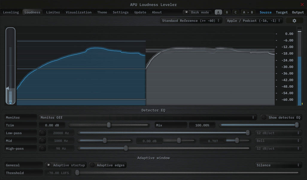
The loudness tab contains parameters relating to loudness measurements and detector behavior.
2.2.1. Detector EQ
Detector EQ shapes the signal used for loudness detection without changing the audible output directly. Use it to emphasize or de-emphasize frequency regions that should carry more or less weight when Loudness Leveler decides how much gain correction to apply.
Detector EQ only affects the detector path. The audible output is unchanged unless detector EQ monitor is enabled for auditioning.
2.2.1.1. Show detector EQ
The show detector EQ parameter allows you to keep the detector EQ response panel visible in the visualization.
If this option is disabled, the detector EQ panel will still appear temporarily while adjusting detector EQ controls.
2.2.1.2. Detector EQ monitor
The monitor mode lets you audition the detector path through the main output. The following options are available:
- Monitor Off: Disable detector auditioning.
- Detector (Post Mix): Audition the detector signal after trim + EQ + mix.
- Pre-EQ: Audition the detector signal before the EQ.
- Post-EQ: Audition the detector signal after the EQ (pre-mix).
- Delta (Wet - Dry): Audition the difference between the EQ’d and dry detector signals.
Monitor does not change detection; it only routes the selected signal to the output for auditioning.
2.2.1.3. Detector EQ trim/mix
The trim and mix parameters control the overall detector EQ gain and blend.
- Trim applies an overall gain offset (dB) to the detector signal.
- Mix crossfades between the dry detector signal (0%) and the EQ’d detector signal (100%).
2.2.1.4. Detector EQ low-pass
The low-pass section filters high frequencies out of the detector signal.
- Enable toggles the low-pass band on/off.
- Frequency sets the cutoff frequency (Hz).
- Slope selects the rolloff: 6, 12, 18, 24, 36, or 48 dB/oct.
2.2.1.5. Detector EQ mid band
The mid band shapes the detector’s sensitivity around a center frequency.
- Enable toggles the mid band on/off.
- Frequency sets the center frequency (Hz).
- Gain boosts/cuts the detector response (dB).
- Q controls bandwidth (higher values = narrower band).
- Shape selects the filter type: Bell, Low shelf, High shelf, or Band-pass.
2.2.1.6. Detector EQ high-pass
The high-pass section filters low frequencies out of the detector signal.
- Enable toggles the high-pass band on/off.
- Frequency sets the cutoff frequency (Hz).
- Slope selects the rolloff: 6, 12, 18, 24, 36, or 48 dB/oct.
2.2.2. Adaptive startup
The adaptive startup parameter enables or disables adaptive startup behavior for loudness measurements. When enabled, the loudness window begins small and grows as the window fills. This can be useful for reducing transient artifacts at the start of playback.
2.2.3. Adaptive edges
The adaptive edges parameter enables or disables adaptive edge detection for loudness measurements. When enabled, loudness values crossing the configured adaptive threshold, or silence, will be detected and the loudness window will be reset. This causes the adaptive startup behavior to apply to every transition to/from silence. This can be useful for reducing transient artifacts during sudden changes in loudness.
2.2.4. Adaptive type
The adaptive type parameter allows adaptive startup and adaptive edges to be configured for Silence or adaptive threshold modes. Silence mode will only reset the loudness window when the input signal is silent. Adaptive threshold mode will reset the loudness window when the input signal crosses the configured adaptive threshold.
2.2.5. Adaptive threshold
The adaptive threshold parameter allows you to configure the threshold used by adaptive edges in adaptive threshold mode. This threshold is specified in the same units as the active measurement implied by timing mode and channel link.
2.3. Limiter
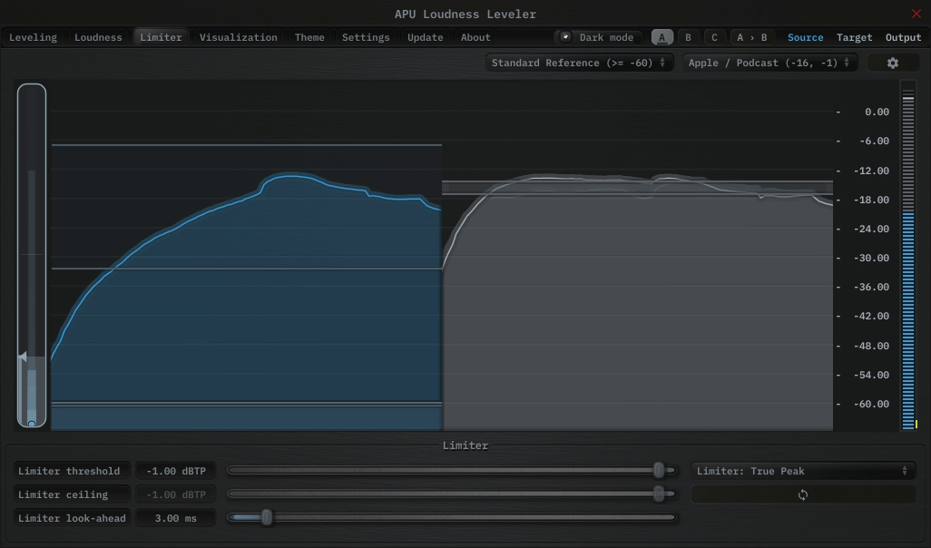
The limiter tab contains parameters relating to the built-in limiter. The limiter scans the limiter lookahead region of blocks for peak or true peak loudness values over the limiter ceiling. When these peaks are encountered, the current gain reduction trajectory is adjusted to accomodate the peak.
2.3.1. Limiter mode
The limiter mode parameter lets you decide which peaks, if any, will be used for detection. The following options are available:
- None: No limiting
- Peak: Digital peaks are detected
- True Peak: Intra-sample peaks are detected according to the LUFS True Peak specification.
2.3.2. Limiter threshold
The limiter threshold parameter determines the loudness at which the limiter starts to apply gain reduction. Loudness values above threshold are raised to the limiter ceiling.
2.3.3. Limiter ceiling
The limiter ceiling parameter determines the maximum peak loudness value that the limiter will allow. When the limiter detects a peak above this value, it will pre-emptively begin to apply gain reduction. Note that make-up gain is not automatically applied.
2.3.4. Limiter threshold link
The limiter threshold link parameter allows you to link the limiter threshold and limiter ceiling parameters. When linked, the ceiling will automatically adjust to match the threshold.
2.3.5. Limiter lookahead
The limiter look-ahead parameter determines the amount of time to look into the future when detecting peaks. Shorter lookahead times will result in more aggressive gain reduction, with the results becoming more gritty and distorted. Longer lookahead times will result in more transparent gain reduction, but will push the average level of the audio further down.
2.4. Visualization
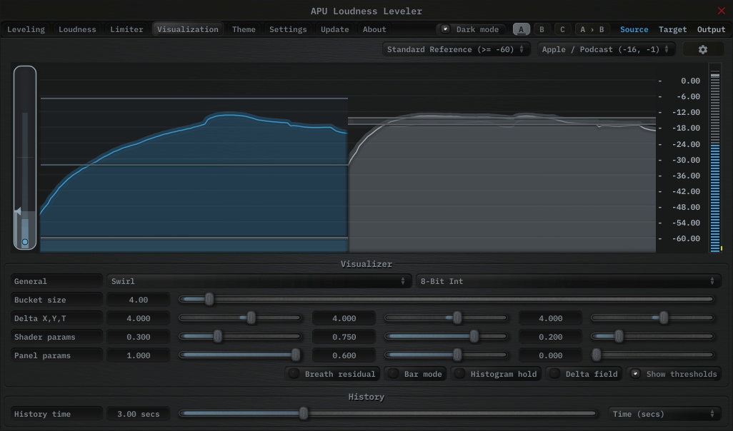
The visualization tab contains parameters related to real-time configuration of Loudness Leveler’s visualizations. This section describes these various settings.
2.4.1. Auto range
The auto range parameter enables or disables the visualization’s auto range finding capabilities. This feature operates by analyzing the continuous histogram at each frame to determine a reasonable range for that moment in time. This range is then followed and adjusted smoothly over time.
2.4.2. Visual range presets
Visual range presets are provided for convenience as an example set of industry related loudness ranges.
Currently, the following visual range presets are available:
- Auto Range (Global)
- Auto Range (Per Panel)
- Standard Reference (>= -60)
- Full Range (>= -70)
- Custom Range …
2.4.3. Loudness range
The loudness range parameter allows the visualization loudness range to be set manually. In order for this range to be enabled and used, the visual range presets parameter must be set to “Custom Range”
Note that there are separate loudness ranges for windowed loudness types and peak loudness types.
See range sliders for information about range sliders in general.
2.4.4. Snapshots
The snapshots feature allows you to take a snapshot of the current histogram. This can be useful for comparing histograms.
Each source/target/output signal has its own snapshot. The snapshots are persisted with plug-in state, so they will be available when you reopen the project.
Snapshots can be operated using the popup menu or via keyboard shortcuts.
The following snapshot parameters are available:
- Save/clear snapshot (saves or clears the current histogram)
- Source = Cmd + 1
- Target = Cmd + 2
- Output = Cmd + 3
- Fill snapshot (fills the area under the snapshot)
- Source = Cmd + Alt + 1
- Target = Cmd + Alt + 2
- Output = Cmd + Alt + 3
- Show/hide snapshot (shows or hides the snapshot in the visualization)
- Source = Cmd + Shift + 1
- Target = Cmd + Shift + 2
- Output = Cmd + Shift + 3
On Windows, use Ctrl instead of Cmd.
2.4.5. Layout options
The options menu allows you to configure the layout of the visualization. The following options are available:
- layout source mode : Specifies the layout mode for the source signal.
- layout target mode : Specifies the layout mode for the target signal.
- layout output mode : Specifies the layout mode for the output signal.
- raster type : Specifies the type of raster visualization.
- show thresholds : Specifies whether or not to show thresholds.
- show detector EQ : Specifies whether or not to keep the detector EQ response panel visible.
- show peak meter : Specifies whether or not to show peak meter.
- show history peak : Specifies whether or not to show history peak hold.
- show axis labels : Specifies whether or not to show loudness axis labels.
- show axis lines : Specifies whether or not to show loudness axis lines.
- show param context : Specifies whether or not to show parameter context while certain parameters are changing.
Each layout mode has an AUTO option which automatically selects the best layout mode based on the current context.
2.4.6. Layout source mode
The layout source mode parameter allows you to configure the layout of the visualization’s source panel.
Currently, the following layout source modes are available:
- None (No source panel is displayed)
- Auto (Automatically selects the best layout mode based on the current context)
- Source only (Draws just the source signal)
- Source over Target (Draws the target signal first, then the source signal on top)
- Source over Output (Draws the output signal first, then the source signal on top)
2.4.7. Layout target mode
The layout target mode parameter allows you to configure the layout of the visualization’s target panel.
Currently, the following layout target modes are available:
- None (No target panel is displayed)
- Auto (Automatically selects the best layout mode based on the current context)
- Target only (Draws just the target signal)
- Target over Source (Draws the source signal first, then the target signal on top)
- Target over Output (Draws the output signal first, then the target signal on top)
2.4.8. Layout output mode
The layout output mode parameter allows you to configure the layout of the visualization’s output panel.
Currently, the following layout output modes are available:
- None (No output panel is displayed)
- Auto (Automatically selects the best layout mode based on the current context)
- Output only (Draws just the output signal)
- Output over Source (Draws the source signal first, then the output signal on top)
- Output over Target (Draws the target signal first, then the output signal on top)
2.4.9. Delta field type
The delta field type parameter allows you to specify the type of delta field used by the visualization.
The delta field is basically a mapping from each source pixel on the screen to a destination pixel. Pixel shaders are used to iteratively apply this delta field using interpolation and some light dithering effects. This feature is purely for aesthetic purposes and has no effect on the audio.
Raster type effects are drawn into the delta field on each frame.
2.4.10. Bits per pixel
The bits-per-pixel parameter determines the number of bits per pixel to use when rendering visualizations. The default bpp is the best performing. You can increase bpp to improve visual quality.
2.4.11. Breath residual
The breath residual parameter can be used to help visualize leveler behavior. For each frame of the visualization, the current residual between target and output loudness is calculated and used to multiply the magnitude of the visualization delta field.
This feature helps you find sections of audio where the leveler is having a difficult time keeping up with the amount of target gain. This can help guide the configuration of the attack/release and linear attack/release parameters. The direction of the multiplication factor is also set to reflect whether the residual occurred in the attack or release direction, so it’s possible to get a sense of the overall balance between these residuals.
2.4.12. Bar Mode
The “Bar mode” parameter enables/disables bar mode. In bar mode, the visualizations will be drawn as vertical bars instead of sloped lines. This feature is purely for aesthetic purposes and has no effect on the audio.
2.4.13. Bucket size
The bucket size parameter determines the size in pixels of visualization buckets (rectangles).
2.4.14. Histogram hold
The histogram hold parameter enables or disables “hold” mode for the histogram raster types. While “hold” mode is enabled, the histogram will continuously accumulate measurements indefinitely. This can be used to capture a full duration view of your source audio. This allows you to easily adjust ranges to target to a specific region of the full dynamic range.
The histogram will still continuously accumulate measurements while “hold” mode is disabled, but for each new measurement the oldest measurement in history is replaced. This results in a continuously evolving histogram of duration specified by the history length parameter.
2.4.15. Delta X/Y/T
The delta X/Y/T parameters are provided to the visualization delta field in order to manipulate the delta field in real-time. The exact behavior of each parameter depends on the active delta field type.
2.4.16. Delta field
The delta field parameter allows you to enable or disable the visualization delta field.
The delta field is basically a mapping from each source pixel on the screen to a destination pixel. Pixel shaders are used to iteratively apply this delta field using interpolation and some light dithering effects. This feature is purely for aesthetic purposes and has no effect on the audio.
Raster type effects are drawn into the delta field on each frame.
2.4.17. Shader params
The shader parameters control various aspects of visualization rendering. The following options are available:
- Shader param 1: Delta field fade rate. Lower values leave longer trails.
- Shader param 2: Curve fill transparency. Lower values make the curve more transparent, leaving only the edge(s) visible.
- Shader param 3: Curve edge thickness. Lower values make the edge thinner.
2.4.18. Show thresholds
The show thresholds parameter allows you to enable or disable threshold drawing in the visualization.
If this option is disabled, thresholds will still be drawn while changing the associated parameters.
Thresholds include target loudness and target tolerance. When editing the shared secondary target, they instead use secondary loudness and secondary tolerance.
2.4.19. Panel params
The panel parameters control various aspects of panel rendering. The following options are available:
- Panel param 1: Panel alpha (transparency), 0.0 to remove panel completely
- Panel param 2: Panel hue (rotates through normal, source, target, output).
- Panel param 3: Panel hue intensity
2.4.20. History length
The history length parameter allows you to change the duration of visualization history. This history is a rolling-window where each new loudness sample pushes out the oldest sample, maintaining a continuous history length with the duration you’ve configured here. Note that this setting applies both to history and histogram raster types.
During histogram hold the histogram has an effectively infinite history length.
2.4.21. Show peak meter
The show peak meter parameter allows you to enable or disable peak meter and gain reduction drawing next to the visualizer.
Positive gain delta is drawn from bottom-up, negative gain delta is drawn from top-down.
The gain delta strip uses yellow for non-limiter gain delta. Orange marks gain reduction attributed to the built-in limiter.
2.4.22. Show history peak
The show history peak parameter allows you to enable or disable peak hold drawing for history raster visualizations.
This option is only shown while the active raster type includes history.
2.4.23. Show axis labels
The show axis labels parameter allows you to enable or disable axis drawing in the visualization.
The axis is scaled relative to the loudness range, which can be manual or auto range.
2.4.24. Show axis lines
The show axis lines parameter allows you to enable or disable axis line drawing in the visualization.
axis lines are drawn at each Show axis labels.
2.4.25. Show param context
The show param context parameter allows you to enable or disable param context text bubbles during parameter changes.
2.5. Theme
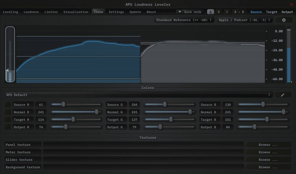
The theme tab contains parameters related to color themes. Here you can select between the bank of color theme presets, or configure the individual colors yourself.
2.5.1. Theme presets
The theme presets combo-box allows you to switch between a variety of theme presets. Each theme has a light and dark variation. Switching between theme presets will load values into source color, normal color, target color and output color.
Currently, the following themes are available:
- APU Default
- APU Red
- APU Vermilion
- APU Orange
- APU Amber
- APU Yellow
- APU Lime
- APU Chartreuse
- APU Harlequin
- APU Green
- APU Erin
- APU Spring
- APU Aquamarine
- APU Cyan
- APU Turquoise
- APU Azure
- APU Cerulean
- APU Blue
- APU Indigo
- APU Violet
- APU Purple
- APU Magenta
- APU Raspberry
- APU Rose
- APU Crimson
2.5.2. Source color
The source color parameters control the red, green, and blue components of the source color.
The source color is used in a variety of contexts, from interactive widgets to visualization elements. This color signifies that an element relates to the source signal in some way. This color is expected to contrast against the normal color to some extent.
2.5.3. Normal color
The normal color parameters control the red, green, and blue components of the “normal” color.
The normal color is used in a variety of contexts, from interactive widgets to visualization elements. This color signifies that an element is essentially neutral, not related to source, target or output signal. This color is expected to contrast against the source color, target color, and output color to some degree.
2.5.4. Target color
The target color parameters control the red, green, and blue components of the target color.
The target color is used in a variety of contexts, from interactive widgets to visualization elements. This color signifies that an element relates to the target signal in some way. This color is expected to contrast against the normal color to some extent.
2.5.5. Output color
The output color parameters control the red, green, and blue components of the output color.
The output color is used in a variety of contexts, from interactive widgets to visualization elements. This color signifies that an element relates to the output signal in some way. This color is expected to contrast against the normal color to some extent.
2.5.6. Textures
The textures configuration allows you to change the user interface textures.
The panel texture is used for the background of the user interface and has the shader params applied. The meter texture is used to fill the visualization effects. The background texture is used throughout the plug-in for shading.
These settings are stored with user scope, so you don’t need to change them with every instance. Closing a texture will reverted to the default internal texture.
Typically, the panel texture should be very dark and the meter texture should be very light.
2.6. Settings
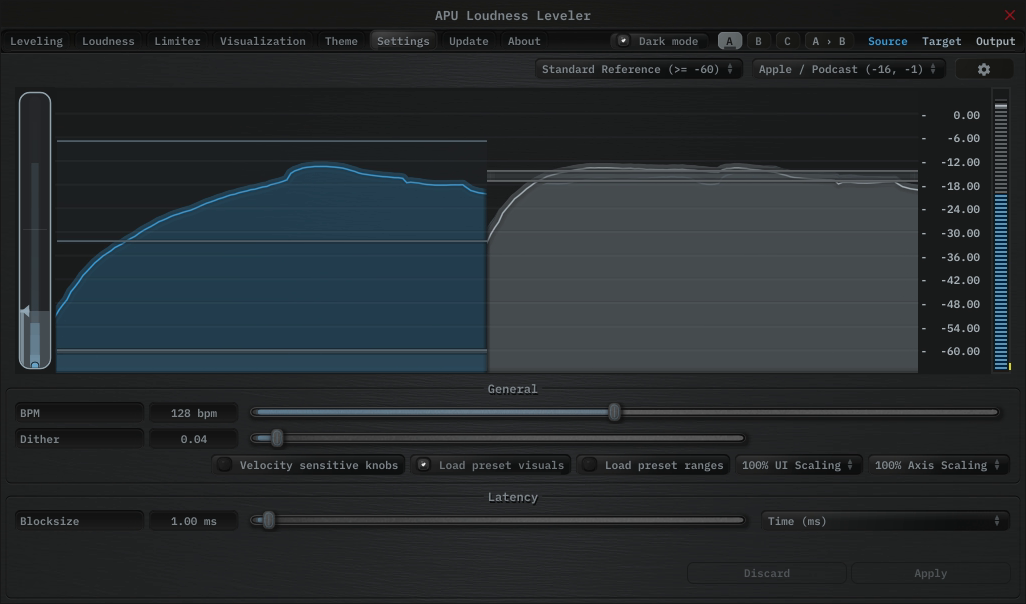
The settings tab contains various additional parameters. These parameters are broken down between General and Latency parameters. Since Latency parameters impact delay compensation, changes to these parameters are deferred until you click the Apply button. It is generally not advisable to automate the parameters in the Latency section.
2.6.1. BPM
The bpm option allows you to set the BPM used by tempo-relative parameters.
2.6.2. Host BPM
The host bpm option enables usage of the host’s BPM for tempo-relative parameters. When disabled, the bpm parameter is used instead.
This parameter is not available (nor applicable) to the standalone application.
2.6.3. Dither
The dither parameter determines the strength of ballistics dithering. This parameter applies only to dithering ballistics type modes.
2.6.4. Velocity sensitive knobs
If enabled, this will turn on velocity-sensitive dragging, so that the faster the mouse moves, the bigger the movement to the knobs. This helps when making accurate small-scale adjustments.
This parameter is saved at user scope, so it will be remembered between sessions.
2.6.5. UI Scaling
The UI scaling option allows you to set the scaling of the user interface. This is useful for high-DPI displays, where the default scaling may be too small to read comfortably.
This parameter is saved at user scope, so it will be remembered between sessions.
2.6.6. Axis Scaling
The axis scaling option allows you to set the scaling of the axis ticks, labels and text bubbles. This is useful for high-DPI displays, where the default scaling may be too small to read comfortably.
This parameter is saved at user scope, so it will be remembered between sessions.
2.6.7. Dark mode
The dark mode toggle enables/disables dark mode. When enabled, theme colors have their brightness inverted.
2.6.8. Gain change write
The gain change write mode controls how the plug-in publishes the latest signed gain change to the host as an automatable parameter. This can be useful for recording the plug-in’s gain changes directly to an automation lane when supported by the DAW.
Disabled turns gain change write off.
Native uses the format-native write path when available. For non-VST3 plug-ins, Native falls back to the same behavior as Compatibility.
Compatibility uses the generic host-notify write path, which may work in more places but is less elegant than Native when the host supports the native path.
Host support for plug-in generated automation varies. When supported, put the host into Write or Touch mode and record the Gain Change Write parameter.
Gain change write is output-only. The recorded automation lane is not read back into the plug-in’s processing.
2.6.9. Blocksize
The block size parameter determines the time resolution of Loudness Leveler’s source loudness measurements. Generally speaking, lower block sizes will give more accurate results. However, lower block sizes also require more CPU resources, so it is necessary to find a balance. You can squeeze improved quality and/or performance out of the leveler by tuning this setting based on your available CPU resources.
Fast attack and/or release times may benefit from similarly low block size.
BPM units for block size are evaluated once at the time you press Apply.
2.6.10. Delay compensation
The delay compensation parameter determines whether or not the plug-in will report latency to the host. Delay compensation is used by hosts to keep audio synchronized across channels.
The delay compensation option is not available (nor applicable) to the standalone application.
2.7. Update
The update tab allows you to check for the latest product versions. Just click “Check for updates” to see the latest version numbers. If you’re not running the latest version, you can click “Download” to open the download page in your default browser.
2.8. About
The about tab contains basic information about the plug-in. This is also where you can activate or deactivate your product keys and check license status.
3. Standalone CLI
APU Loudness Leveler’s standalone application exposes a small user-facing command-line interface for loading, saving, and resetting standalone preset files. This section documents the supported options only.
Supported options:
--helpprints the supported standalone CLI options and exits.--resetParamsresets parameters after the standalone app loads its remembered state.--loadPreset="<path>"loads a preset file before the window is shown.--savePreset="<path>"writes the resulting preset file and exits without opening the user interface.
Processing order:
- The standalone app first loads its normal remembered standalone state.
- If
--resetParamsis present, a full parameter reset is applied. - If
--loadPresetis present, that preset file is loaded next. - If
--savePresetis present, the resulting state is written to disk and the app exits immediately.
Examples:
<standalone-app> --help<standalone-app> --savePreset="C:\Temp\leveler-startup.preset"<standalone-app> --resetParams --savePreset="C:\Temp\leveler-reset.preset"<standalone-app> --loadPreset="/tmp/leveler-session.preset"<standalone-app> --loadPreset="/tmp/leveler-session.preset" --savePreset="/tmp/leveler-copy.preset"
Compatibility:
--loadPresetand--savePresetuse the same file format as the standalone app’s standard JUCE options-button commands,Save current state...andLoad a saved state....- These file-based presets store the full standalone processor state. They are different from the in-app presets combo-box, which loads the product’s built-in preset entries and user preset-list selections.
4. Glossary
This section defines some of the concepts used within the software.
4.1. Range sliders
Range sliders are used throughout the plug-in in order to specify the upper and lower boundaries of a range. These ranges can be controlled via mouse in various ways.
- Click and drag the lower thumb to adjust the minimum value.
- Click and drag the upper thumb to adjust the maximum value.
- Click and drag the region between slider thumbs to move both values. This allows you to adjust the average loudness without expanding/contracting the dynamic range.
- Ctrl + click and drag the region between slider thumbs to expand/contract range without changing the average (center) value. Drag the mouse up and down, left and right are ignored.
- Shift + click and drag the region between slider thumbs to combine both. Drag the mouse up and down to expand/contract range. Drag the mouse left and right to move both values.
4.2. History
One of the primary views into your audio that this software provides is real-time history. The history view maintains a recent history of loudness measurements, continuously displaying them in FIFO order. This view helps you understand how the signal is changing over time, in real-time. History length and bucket size can be configured dynamically without forcing the history to reset.
4.3. Histogram
One of the primary views into your audio that this software provides is a real-time histogram. Histograms in general provide a quick and intuitive way to understand the relative frequency of different measurements. This is very useful when judging the overall dynamic range of the audio. The histogram provided by this software is capable of changing history length, bucket size and size continuously.
4.4. Source
The term “source” is used throughout the plug-in to identify the plug-in’s input source signal. This signal is represented in the user interface by the current theme’s source color.
4.5. Target
The term “target” is used throughout the plug-in to identify the configured target range loudness. This signal is represented in the user interface by the current theme’s target color.
4.6. Output
The term “output” is used throughout the plug-in to identify the output type signal. This signal is represented in the user interface by the current theme’s output color.
5. Credits
This software was developed by APU Software, LLC and is available as VST (windows x64/x86, macOS universal), Audio Unit (macOS universal), Pro Tools AAX (windows x64, macOS universal), or Standalone Application (windows x64/x86, macOS universal). The software libraries below are utilized for portions of the software:
- JUCE (cross-platform audio and user interface framework)
- Boost (header-only algorithms)
- libebur128 (loudness measurements)
- melatonin_blur (blur effects)
Demo video song credits:
- Titan Sound - Technology Flow, licensed via PremiumBeat


5.1. MIT License (libebur128)
Copyright (c) 2011 Jan Kokemüller
Permission is hereby granted, free of charge, to any person obtaining a copy
of this software and associated documentation files (the "Software"), to deal
in the Software without restriction, including without limitation the rights
to use, copy, modify, merge, publish, distribute, sublicense, and/or sell
copies of the Software, and to permit persons to whom the Software is
furnished to do so, subject to the following conditions:

The above copyright notice and this permission notice shall be included in
all copies or substantial portions of the Software.

THE SOFTWARE IS PROVIDED "AS IS", WITHOUT WARRANTY OF ANY KIND, EXPRESS OR
IMPLIED, INCLUDING BUT NOT LIMITED TO THE WARRANTIES OF MERCHANTABILITY,
FITNESS FOR A PARTICULAR PURPOSE AND NONINFRINGEMENT. IN NO EVENT SHALL THE
AUTHORS OR COPYRIGHT HOLDERS BE LIABLE FOR ANY CLAIM, DAMAGES OR OTHER
LIABILITY, WHETHER IN AN ACTION OF CONTRACT, TORT OR OTHERWISE, ARISING FROM,
OUT OF OR IN CONNECTION WITH THE SOFTWARE OR THE USE OR OTHER DEALINGS IN
THE SOFTWARE.
5.2. MIT License (melatonin_blur)
Copyright (c) 2023 Sudara Williams
Permission is hereby granted, free of charge, to any person obtaining a copy
of this software and associated documentation files (the "Software"), to deal
in the Software without restriction, including without limitation the rights
to use, copy, modify, merge, publish, distribute, sublicense, and/or sell
copies of the Software, and to permit persons to whom the Software is
furnished to do so, subject to the following conditions:

The above copyright notice and this permission notice shall be included in all
copies or substantial portions of the Software.

THE SOFTWARE IS PROVIDED "AS IS", WITHOUT WARRANTY OF ANY KIND, EXPRESS OR
IMPLIED, INCLUDING BUT NOT LIMITED TO THE WARRANTIES OF MERCHANTABILITY,
FITNESS FOR A PARTICULAR PURPOSE AND NONINFRINGEMENT. IN NO EVENT SHALL THE
AUTHORS OR COPYRIGHT HOLDERS BE LIABLE FOR ANY CLAIM, DAMAGES OR OTHER
LIABILITY, WHETHER IN AN ACTION OF CONTRACT, TORT OR OTHERWISE, ARISING FROM,
OUT OF OR IN CONNECTION WITH THE SOFTWARE OR THE USE OR OTHER DEALINGS IN THE
SOFTWARE.