1. Introduction
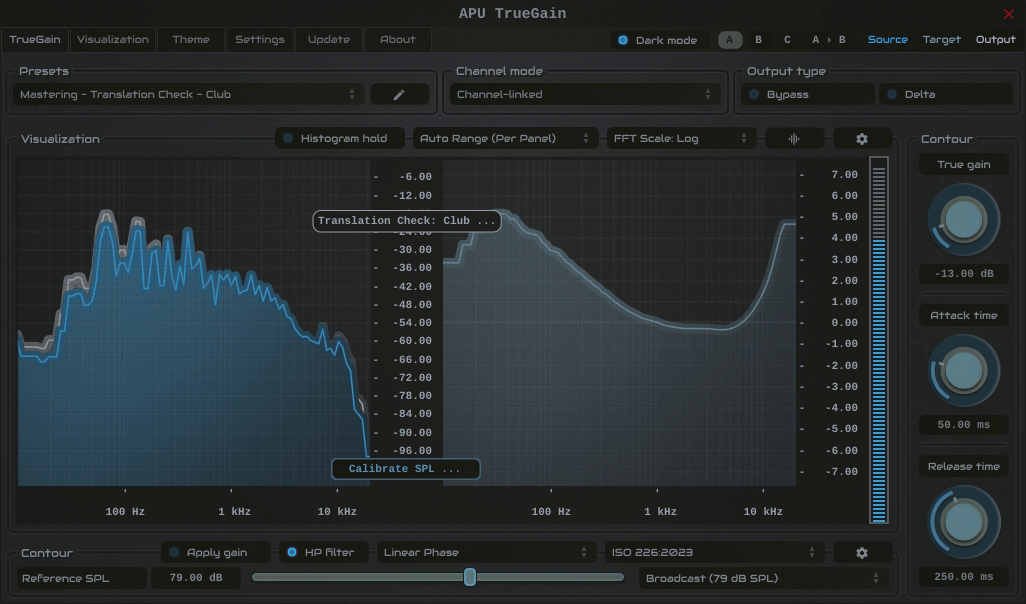
APU TrueGain is an ‘equal-loudness’ contour based gain correction plug-in released by APU Software, LLC. Here you can read about the different features and parameters available with the plug-in.
2. Parameters
This software supports a variety of parameters, most of which can be adjusted in real-time. This section provides an overview of each parameter, with each subsection detailing the parameters for the associated tab in the user interface. From within the user interface, you can also hover the mouse over a slider, combo-box, or checkbox to see a popup description of the parameter.
2.1. TrueGain
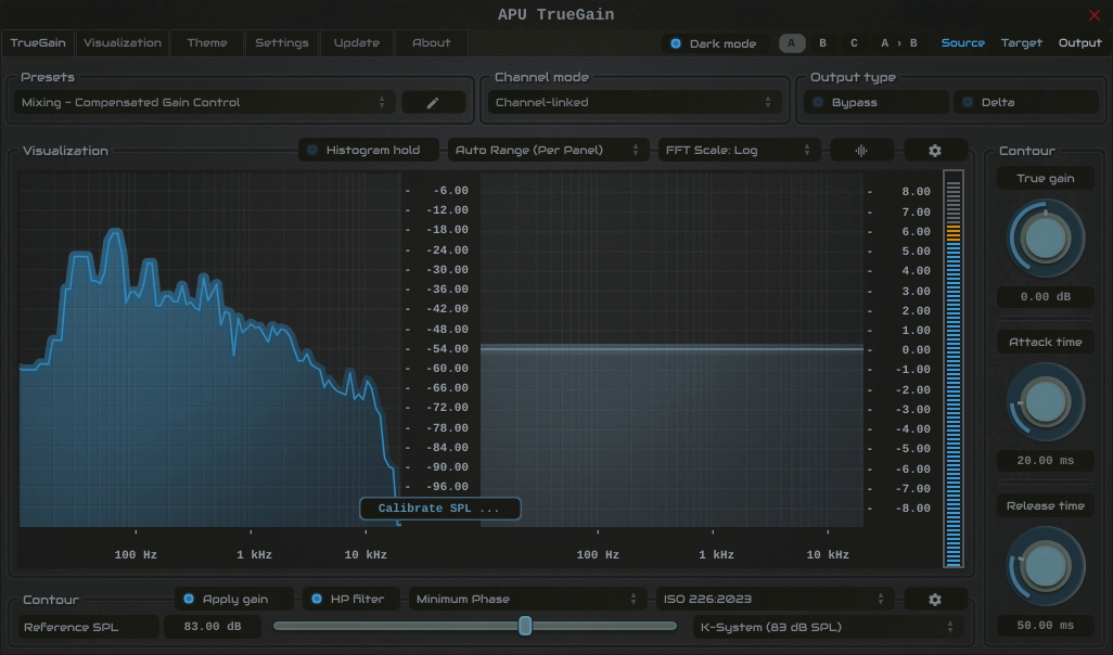
The TrueGain tab contains configuration and visualization for equal-loudness based gain compensation. This section details each of the individual parameters and components.
TrueGain also supports mini mode for a compact control-focused layout.
Calibration gives TrueGain a reference for estimating the sound pressure level at your listening position. Place TrueGain before room/headphone correction or crossfeed in your monitoring chain, and keep those processors enabled during calibration.
Calibration for Speaker Monitoring:
- Place an SPL meter at your listening position, using C-weighting and a slow response.
- Click “Calibrate SPL …”, then select Speakers: Pink Noise (Band-Limited) from calibration signal type. A 1 kHz sine wave and full-bandwidth pink noise are also available.
- Play one speaker at a time using your monitor controls. At your chosen monitoring volume, set reference SPL to the meter reading. If you are using a reference-level preset, adjust each speaker’s playback level to match it.
- Click “Stop calibration” and restore normal speaker routing. Keep your monitor volume and downstream processing at their calibrated settings.
For Bob Katz’s K-System, the K-20 reference is 83 dBC SPL per speaker, measured one speaker at a time with pink noise at -20 dBFS RMS (+3). The reference-level drop-down offers common examples; choose the level appropriate to your monitoring setup.
Calibration Signal Levels:
The built-in speaker signals are normalized to -20 dBFS on a sine-referenced RMS (+3) meter, equivalent to approximately -23.01 dBFS mathematical RMS. This RMS reference does not define a fixed LUFS value for program material.
The built-in band-limited pink noise covers 500-2500 Hz. Its stored mono K-weighted calibration measurement is approximately -22.22 LUFS. The EBU reference listening signal covers 500-2000 Hz and is normalized to -23 LUFS. Their bandwidths and normalization targets differ. Adaptive SPL uses the stored measurement for the selected calibration signal and loudness type.
Calibration for Headphone Monitoring:
- Keep your headphone volume at your chosen listening setting, with headphone correction and crossfeed enabled if you normally use them.
- Click “Calibrate SPL …”, then select Headphones: Dialog (Male) or Headphones: Dialog (Female) from calibration signal type.
- Adjust calibration offset until the spoken dialog sounds like a normal conversation from about 3 feet away in a quiet room, then click “Stop calibration”.
While headphone calibration plays, reference SPL updates automatically using Reference SPL = 65 - Calibration offset, in dB SPL. The 65 dB anchor is the plugin’s conversational reference. Dialogue matching provides a subjective estimate of listening level, not a direct measurement of headphone SPL.
Keep the selected calibration signal type after stopping playback so adaptive SPL uses the same baseline. Calibration anchors the contour model to your playback setup; its loudness compensation remains an estimate. Repeat calibration after changing monitor volume or downstream processing.
2.1.1. Presets
TrueGain’s presets combo-box contains a collection of basic presets.
The preset browser includes user-scope load options for ordinary preset changes. Reset on preset load runs a filtered parameter reset before the preset is applied. Load preset visuals controls whether the preset can change the hinted theme and visualization settings. Full Reset always restores all default parameter values, regardless of these options. You can switch between loading dark or light themes through the dark mode parameter.
Currently, the following presets are available (“Full Reset” restores all default parameter values):
- Full Reset
- Mixing - Compensated Gain Control
- Mixing - Compensated AGC (± 6 dB)
- Mixing - Compensated AGC (± 12 dB)
- Mixing - Translation Check - Quiet
- Mixing - Translation Check - Casual
- Mixing - Translation Check - Broadcast
- Mixing - Translation Check - Cinematic
- Mixing - Translation Check - Club
- Mastering - Compensated Gain Control
- Mastering - Compensated AGC (± 6 dB)
- Mastering - Compensated AGC (± 12 dB)
- Mastering - Translation Check - Quiet
- Mastering - Translation Check - Casual
- Mastering - Translation Check - Broadcast
- Mastering - Translation Check - Cinematic
- Mastering - Translation Check - Club
2.1.2. Channel mode
The channel mode parameter determines which channel the visualizer shows. Channel-linked shows the average of all channels, while channel-select shows only the selected channel.
2.1.3. Output type
The output type options allows you to configure which type of samples to output.
- Default output type corresponds to TrueGain’s output
- Bypass output type corresponds to TrueGain’s source
- Delta output type corresponds to TrueGain’s output minus source
Output gain and dry/wet are bypassed for Delta output type
2.1.4. Visualization
The visualization component displays a continuously evolving real-time view of your source, target, and output spectrum over time.
You can hover the mouse over a bucket to see the frequency range and loudness the bucket corresponds to.
Detailed visualization settings can be adjusted from the visualization tab, with some features also available by right clicking on the visualization component.
You can double-click the visualization component to resize and hide everything else.
2.1.5. Mini mode
The mini mode button in the upper-right of the editor switches TrueGain into a compact editor layout. This is useful when you want to keep TrueGain visible while working elsewhere in the session without taking up the full editor area.
In mini mode, TrueGain keeps the most relevant control for the current true gain mode visible. Compensated Gain Control and Gain Control show true gain, while Compensated AGC and Translation Check show target SPL. A small peak meter remains visible to the right.
Use the expand button in the upper-right corner of mini mode to switch back to the full editor.
2.1.6. FFT scale type
The FFT scale type parameter determines the frequency scale used for the visualization. The following options are available:
- Linear: Linear frequency scale with frequency labels
- Log: Logarithmic frequency scale with frequency labels
- Note: Logarithmic frequency scale with note labels
2.1.7. FFT window type
The FFT window type parameter determines the window type used for the spectral histogram’s FFT. The following options are available:
- Rect: Rectangular window
- Hann: Hann window
- Hamming: Hamming window
- Blackman: Blackman window
- Kaiser: Kaiser window
When using the Kaiser window, the Kaiser beta parameter is used to determine the window shape.
2.1.8. FFT window size
The FFT window size parameter determines the size of the spectral histogram’s FFT window.
The FFT window size determines a trade-off between frequency resolution and time resolution. A larger window size provides better frequency resolution, while a smaller window size provides better time resolution.
2.1.9. Kaiser beta
The Kaiser beta parameter determines the shape of the window when Kaiser FFT window type is selected.
2.1.10. Raster type
The raster type parameter allows you to enable/disable the spectral histogram raster visualization.
2.1.11. Raster orientation
The raster orientation parameter allows you to specify the rotation of the raster visualization. You can select between horizontal and vertical orientations.
2.1.12. Play calibration signal
The play calibration signal parameter allows you to play a calibration signal through the source signal. This allows you to calibrate reference SPL with your playback system.
Calibration signal type determines the type of calibration signal played.
See TrueGain for general calibration process
2.1.13. Calibration signal type
The calibration signal type parameter determines the type of calibration signal played when play calibration signal is enabled. The following options are available:
- Speakers: Pink Noise (Band-Limited)
- Speakers: Sine Wave at 1 kHz
- Speakers: Pink Noise (Full Bandwidth)
- Headphones: Dialog (Male)
- Headphones: Dialog (Female)
See TrueGain for general calibration process
2.1.14. Calibration offset
The calibration offset parameter is used to help calibrate the Reference SPL as part of the headphones calibration process.
See TrueGain for general calibration process
2.1.15. Adaptive SPL
Adaptive SPL adjusts the effective reference SPL used for loudness contour processing as the input level changes. The reference SPL control remains the calibrated baseline.
The adjustment is calculated by subtracting the stored loudness of the selected calibration signal type from the current input loudness. This difference is limited by the minimum and maximum reference offset settings, then added to reference SPL.
The input measurement and stored calibration baseline use the current loudness type, including its measurement window and, for LUFS measurements, the weighting selected by IIR contour type. When using a channel-split loudness type, the adjustment is calculated separately for each channel. The selected calibration signal remains the baseline when play calibration signal is switched off.
Example: Select Speakers: Pink Noise (Band-Limited), Momentary loudness and K-weighting. The stored calibration baseline is -22.22 LUFS. With reference SPL set to 83 dB SPL and an input reading of -16.22 LUFS:
- Input difference:
-16.22 - (-22.22) = +6 dB. - Effective reference SPL:
83 + 6 = 89 dB SPL, provided the reference offset limits allow +6 dB.
This is an estimate relative to your selected calibration signal and calibrated playback level. It assumes the playback system remains at its calibrated settings.
In Compensated Gain Control true gain mode, Adaptive SPL changes the contour reference while true gain continues to set the gain adjustment.
For automatic gain adjustment toward a fixed target SPL, enable Adaptive SPL and use Compensated AGC. The gain limits and attack/release (ms) smoothing determine the amount and speed of correction.
2.1.16. True gain mode
The true gain mode parameter determines the mode used for true gain processing. The following options are available:
- Compensated Gain Control: True gain is used to apply gain and frequency compensation to the source signal. Maintains frequency balance while adjusting loudness.
- Compensated AGC: Target SPL is used to determine both the amount of gain applied to the source signal and the frequency compensation applied to the source signal. Can be used for SPL-based automatic gain control.
- Translation Check: Target SPL is used to determine the frequency compensation (only) applied to the source signal. Can be used to check how a mix translates at different SPLs, while maintaining monitoring level.
- Gain Control: True gain is used to apply gain (only) to the source signal. Does not maintain frequency balance while adjusting loudness.
See Worked examples for settings that separate contour compensation from scalar gain.
The target SPL parameter is hidden while either Gain Control mode is active, since it is not used in these modes.
2.1.17. Phase mode
The phase mode parameter determines the phase mode used for the FIR filters. The following options are available:
- Minimum: Minimum phase mode
- Linear: Linear phase mode
2.1.18. SPL contour type
The SPL contour type parameter determines the type of loudness contour used for gain compensation. The following options are available:
- ISO-226:2003
- ISO-226:2023
- Fletcher-Munson
2.1.19. Ballistics type
The ballistics type combo-box allows you to change TrueGain’s ballistics behavior.
- Natural (dithered) applies light dithering to natural ballistics deltas.
- Natural (direct) applies normal smooth attack and release ballistics.
- Inertial (dithered) applies light dithering to inertial ballistics deltas.
- Inertial (direct) applies attack and release ballistics with inertia.
Inertial ballistics are more responsive to sudden changes in loudness, but may sound less natural.
2.1.20. Reference SPL
The reference SPL parameter determines the baseline sound pressure level used for gain-correction and translation checks.
See TrueGain for general calibration process
2.1.21. Target SPL
The target SPL parameter determines the target sound pressure level used for Compensated AGC and Translation Check true gain mode.
See TrueGain for general calibration process
2.1.22. True gain
The true gain parameter determines the amount of gain and/or frequency-compensated gain applied to the source signal. See true gain mode for more information.
True gain is hidden while Compensated AGC or Translation Check mode is active, since it is not used in these modes.
2.1.23. Max range
The max range parameter allows you to specify the max gain reduction or gain amplification for the associated True Gain parameter. Note this parameter has a positive and a negative version, so you can set them independently.
2.1.24. Attack/release (ms)
The attack and release parameters allow you to smooth changes made to gain and frequency parameters.
Attack applies when a parameter is falling, while release applies when a parameter is rising.
2.2. Loudness
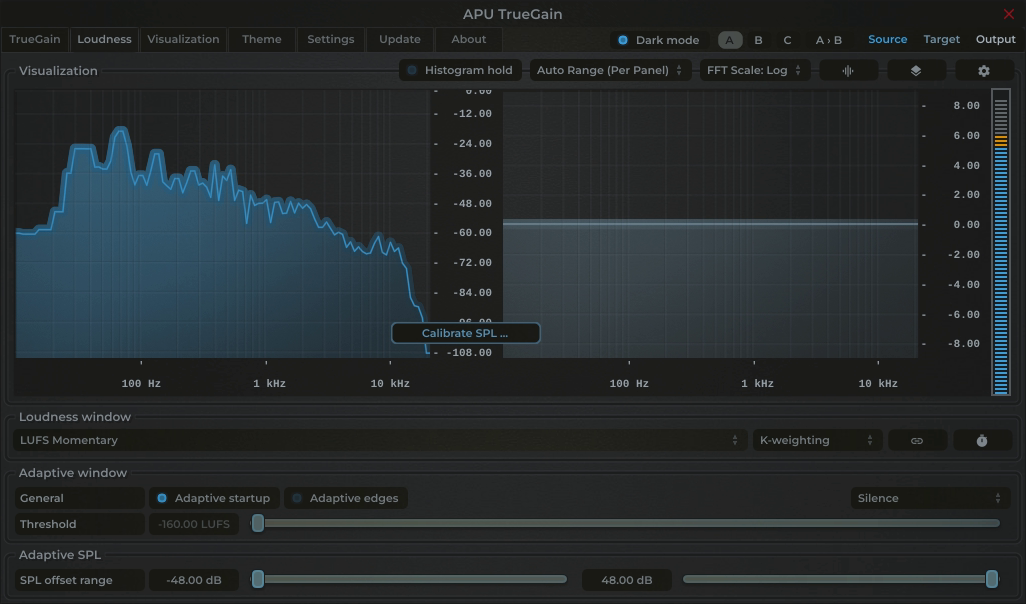
The loudness tab contains parameters relating to loudness measurements and detector behavior.
2.2.1. Loudness type
The loudness type combo-box and channel-link button allow you to configure the type of loudness measurement to use. Each loudness type supports channel-split or channel-linked processing. Channel-split treats each channel independently, while channel-linked integrates across all channels.
Three of the supported loudness types use a popular modern measurement standard for perceived loudness called LUFS. These loudness types are momentary (400ms window), short-term (3s window) and Integrated (infinite window).
There are also two peak loudness types (True Peak and Peak) as well as traditional RMS. True Peak is an improvement on peak which takes into consideration waveform behavior between samples, which allows it to properly respond to inter-sample peaks. Peak mode loudness types use a blocksize window.
Integrated loudness type window can be reset by pressing the reset button.
2.2.2. IIR contour type
The IIR contour type combo-box allows you to change the LUFS loudness type’s IIR filter contour. The following contours are supported:
- K-weighting
- ECMA-418
- ITU-R 468
- A-weighting
- C-weighting
Contours other than K-weighting no longer conform to the LUFS standard, but are provided for flavor and perceptual precision.
2.2.3. RMS window
The RMS window parameter allows you to adjust the duration of the RMS window in milliseconds. Lower window durations respond more quickly to changes in loudness, while higher window durations provide a more stable loudness measurement. The RMS window is used by the RMS loudness type.
2.2.4. Momentary window
The momentary window parameter allows you to adjust the duration of the momentary window in milliseconds. Lower window durations respond more quickly to changes in loudness, while higher window durations provide a more stable loudness measurement. The momentary window is used by the Momentary loudness type.
2.2.5. Short-term window
The short-term window parameter allows you to adjust the duration of the short-term window in milliseconds. Lower window durations respond more quickly to changes in loudness, while higher window durations provide a more stable loudness measurement. The short-term window is used by the Short-term loudness type.
2.2.6. Adaptive startup
The adaptive startup parameter enables or disables adaptive startup behavior for loudness measurements. When enabled, the loudness window begins small and grows as the window fills. This can be useful for reducing transient artifacts at the start of playback.
2.2.7. Adaptive edges
The adaptive edges parameter enables or disables adaptive edge detection for loudness measurements. When enabled, loudness values crossing the configured adaptive threshold, or silence, will be detected and the loudness window will be reset. This causes the adaptive startup behavior to apply to every transition to/from silence. This can be useful for reducing transient artifacts during sudden changes in loudness.
2.2.8. Adaptive type
The adaptive type parameter allows adaptive startup and adaptive edges to be configured for Silence or adaptive threshold modes. Silence mode will only reset the loudness window when the input signal is silent. Adaptive threshold mode will reset the loudness window when the input signal crosses the configured adaptive threshold.
2.2.9. Adaptive threshold
The adaptive threshold parameter allows you to configure the threshold used by adaptive edges in adaptive threshold mode. This threshold is specified in the same units as the current loudness type.
2.2.10. Look-ahead
The look-ahead parameter allows you to configure how far in advance the loudness measurement looks for the source signal. This can be used to align TrueGain’s response to account for the loudness window time and/or attack/release times, or simply as a creative effect.
Look-ahead requires that the look-ahead budget parameter is configured via the settings tab. This method of look-ahead configuration is used to support real-time adjustments of look-ahead without causing stuttering which would otherwise interfere with A/B testing.
Note that look-ahead budget adds latency to the truegain in order to function.
2.2.11. Reference Offset
The reference offset parameter determines the min/max offset applied to the reference SPL used for the contour filter for adaptive SPL.
See TrueGain for general calibration process
2.3. Visualization
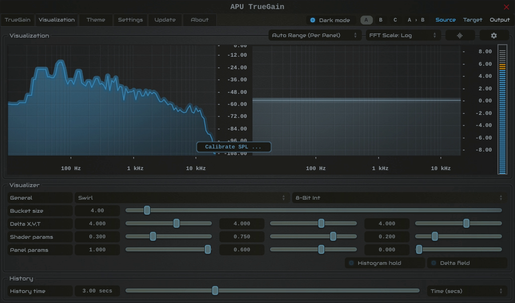
The visualization tab contains parameters related to real-time configuration of TrueGain’s visualizations. This section describes these various settings.
2.3.1. Auto range
The auto range parameter enables or disables the visualization’s auto range finding capabilities. This feature operates by analyzing the continuous histogram at each frame to determine a reasonable range for that moment in time. This range is then followed and adjusted smoothly over time.
2.3.2. Visual range presets
Visual range presets are provided for convenience to quickly adjust the dB range of the visualizer.
Currently, the following visual range presets are available:
- Auto Range (Global)
- Auto Range (Per Panel)
- Standard Reference (>= -90)
- Deep Range (>= -120)
- Full Range (>= -160)
- Custom Range …
2.3.3. Loudness range
The loudness range parameter allows the visualization loudness range to be set manually. In order for this range to be enabled and used, the visual range presets parameter must be set to “Custom Range”
See range sliders for information about range sliders in general.
2.3.4. Snapshots
The snapshots feature allows you to take a snapshot of the current histogram. This can be useful for comparing histograms.
Each source/target/output signal has its own snapshot. The snapshots are persisted with plug-in state, so they will be available when you reopen the project.
Snapshots can be operated using the popup menu or via keyboard shortcuts.
The following snapshot parameters are available:
- Save/clear snapshot (saves or clears the current histogram)
- Source = Cmd + 1
- Target = Cmd + 2
- Output = Cmd + 3
- Fill snapshot (fills the area under the snapshot)
- Source = Cmd + Alt + 1
- Target = Cmd + Alt + 2
- Output = Cmd + Alt + 3
- Show/hide snapshot (shows or hides the snapshot in the visualization)
- Source = Cmd + Shift + 1
- Target = Cmd + Shift + 2
- Output = Cmd + Shift + 3
On Windows, use Ctrl instead of Cmd.
2.3.5. Layout options
The options menu allows you to configure the layout of the visualization. The following options are available:
- layout source mode : Specifies the layout mode for the source signal.
- layout target mode : Specifies the layout mode for the target signal.
- layout output mode : Specifies the layout mode for the output signal.
- raster type : Specifies the type of raster visualization.
- raster orientation : Specifies the orientation of the raster visualization.
- show contour : Specifies whether or not to show the current contour for all panels
- show peak meter : Specifies whether or not to show peak meter.
- show spectrum peak : Specifies whether or not to show spectral peak.
- show axis labels : Specifies whether or not to show loudness axis labels.
- show axis lines : Specifies whether or not to show loudness axis lines.
- show alt axis labels : Specifies whether or not to show frequency axis labels.
- show alt axis lines : Specifies whether or not to show frequency axis lines.
Each layout mode has an AUTO option which automatically selects the best layout mode based on the current context.
2.3.6. Layout source mode
The layout source mode parameter allows you to configure the layout of the visualization’s source panel.
Currently, the following layout source modes are available:
- None (No source panel is displayed)
- Auto (Automatically selects the best layout mode based on the current context)
- Source only (Draws just the source signal)
- Source over Target (Draws the target signal first, then the source signal on top)
- Source over Output (Draws the output signal first, then the source signal on top)
2.3.7. Layout target mode
The layout target mode parameter allows you to configure the layout of the visualization’s target panel.
Currently, the following layout target modes are available:
- None (No target panel is displayed)
- Auto (Automatically selects the best layout mode based on the current context)
- Target only (Draws just the target signal)
- Target over Source (Draws the source signal first, then the target signal on top)
- Target over Output (Draws the output signal first, then the target signal on top)
2.3.8. Layout output mode
The layout output mode parameter allows you to configure the layout of the visualization’s output panel.
Currently, the following layout output modes are available:
- None (No output panel is displayed)
- Auto (Automatically selects the best layout mode based on the current context)
- Output only (Draws just the output signal)
- Output over Source (Draws the source signal first, then the output signal on top)
- Output over Target (Draws the target signal first, then the output signal on top)
2.3.9. Delta field type
The delta field type parameter allows you to specify the type of delta field used by the visualization.
The delta field is basically a mapping from each source pixel on the screen to a destination pixel. Pixel shaders are used to iteratively apply this delta field using interpolation and some light dithering effects. This feature is purely for aesthetic purposes and has no effect on the audio.
Raster type effects are drawn into the delta field on each frame.
2.3.10. Bits per pixel
The bits-per-pixel parameter determines the number of bits per pixel to use when rendering visualizations. The default bpp is the best performing. You can increase bpp to improve visual quality.
2.3.11. Bar Mode
The “Bar mode” parameter enables/disables bar mode. In bar mode, the visualizations will be drawn as vertical bars instead of sloped lines. This feature is purely for aesthetic purposes and has no effect on the audio.
2.3.12. Bucket size
The bucket size parameter determines the size in pixels of visualization buckets (rectangles).
2.3.13. Histogram hold
The histogram hold parameter enables or disables “hold” mode for the histogram raster types. While “hold” mode is enabled, the histogram will continuously accumulate measurements indefinitely. This can be used to capture a full duration view of your source audio. This allows you to easily adjust ranges to target to a specific region of the full dynamic range.
The histogram will still continuously accumulate measurements while “hold” mode is disabled, but for each new measurement the oldest measurement in history is replaced. This results in a continuously evolving histogram of duration specified by the history length parameter.
2.3.14. Delta X/Y/T
The delta X/Y/T parameters are provided to the visualization delta field in order to manipulate the delta field in real-time. The exact behavior of each parameter depends on the active delta field type.
2.3.15. Delta field
The delta field parameter allows you to enable or disable the visualization delta field.
The delta field is basically a mapping from each source pixel on the screen to a destination pixel. Pixel shaders are used to iteratively apply this delta field using interpolation and some light dithering effects. This feature is purely for aesthetic purposes and has no effect on the audio.
Raster type effects are drawn into the delta field on each frame.
2.3.16. Shader params
The shader parameters control various aspects of visualization rendering. The following options are available:
- Shader param 1: Delta field fade rate. Lower values leave longer trails.
- Shader param 2: Curve fill transparency. Lower values make the curve more transparent, leaving only the edge(s) visible.
- Shader param 3: Curve edge thickness. Lower values make the edge thinner.
2.3.17. Show contour
The show contour parameter allows you to enable or disable contour drawing in the visualization.
Show contour applies to all panels in the visualization, including source, target, and output signals.
2.3.18. Panel params
The panel parameters control various aspects of panel rendering. The following options are available:
- Panel param 1: Panel alpha (transparency), 0.0 to remove panel completely
- Panel param 2: Panel hue (rotates through normal, source, target, output).
- Panel param 3: Panel hue intensity
2.3.19. History length
The history length parameter allows you to change the duration of spectral history accumulated by the histogram. Each new spectrum sample contributes to the histogram while the oldest samples age out, maintaining the duration you’ve configured here.
During histogram hold the histogram has an effectively infinite history length.
2.3.20. Show peak meter
The show peak meter parameter allows you to enable or disable peak meter drawing next to the visualizer.
2.3.21. Show spectrum peak
The show spectrum peak parameter allows you to enable or disable spectral peak drawing.
2.3.22. Show axis labels
The show axis labels parameter allows you to enable or disable axis drawing in the visualization.
The axis is scaled relative to the loudness range, which can be manual or auto range.
2.3.23. Show axis lines
The show axis lines parameter allows you to enable or disable axis line drawing in the visualization.
axis lines are drawn at each Show axis labels.
2.3.24. Show alt axis labels
The show axis labels parameter allows you to enable or disable frequency axis drawing in the visualization.
2.3.25. Show alt axis lines
The show axis lines parameter allows you to enable or disable frequency axis line drawing in the visualization.
axis lines are drawn at each Show alt axis labels.
2.4. Theme
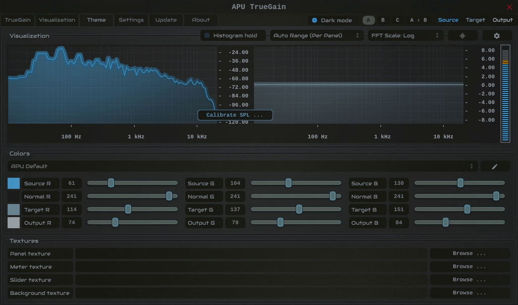
The theme tab contains parameters related to color themes. Here you can select between the bank of color theme presets, or configure the individual colors yourself.
2.4.1. Theme presets
The theme presets combo-box allows you to switch between a variety of theme presets. Each theme has a light and dark variation. Switching between theme presets will load values into source color, normal color, target color and output color.
Currently, the following themes are available:
- APU Default
- APU Red
- APU Vermilion
- APU Orange
- APU Amber
- APU Yellow
- APU Lime
- APU Chartreuse
- APU Harlequin
- APU Green
- APU Erin
- APU Spring
- APU Aquamarine
- APU Cyan
- APU Turquoise
- APU Azure
- APU Cerulean
- APU Blue
- APU Indigo
- APU Violet
- APU Purple
- APU Magenta
- APU Raspberry
- APU Rose
- APU Crimson
2.4.2. Source color
The source color parameters control the red, green, and blue components of the source color.
The source color is used in a variety of contexts, from interactive widgets to visualization elements. This color signifies that an element relates to the source signal in some way. This color is expected to contrast against the normal color to some extent.
2.4.3. Normal color
The normal color parameters control the red, green, and blue components of the “normal” color.
The normal color is used in a variety of contexts, from interactive widgets to visualization elements. This color signifies that an element is essentially neutral, not related to source, target or output signal. This color is expected to contrast against the source color, target color, and output color to some degree.
2.4.4. Target color
The target color parameters control the red, green, and blue components of the target color.
The target color is used in a variety of contexts, from interactive widgets to visualization elements. This color signifies that an element relates to the target signal in some way. This color is expected to contrast against the normal color to some extent.
2.4.5. Output color
The output color parameters control the red, green, and blue components of the output color.
The output color is used in a variety of contexts, from interactive widgets to visualization elements. This color signifies that an element relates to the output signal in some way. This color is expected to contrast against the normal color to some extent.
2.4.6. Textures
The textures configuration allows you to change the user interface textures.
The panel texture is used for the background of the user interface and has the shader params applied. The meter texture is used to fill the visualization effects. The background texture is used throughout the plug-in for shading.
These settings are stored with user scope, so you don’t need to change them with every instance. Closing a texture will reverted to the default internal texture.
Typically, the panel texture should be very dark and the meter texture should be very light.
2.5. Settings
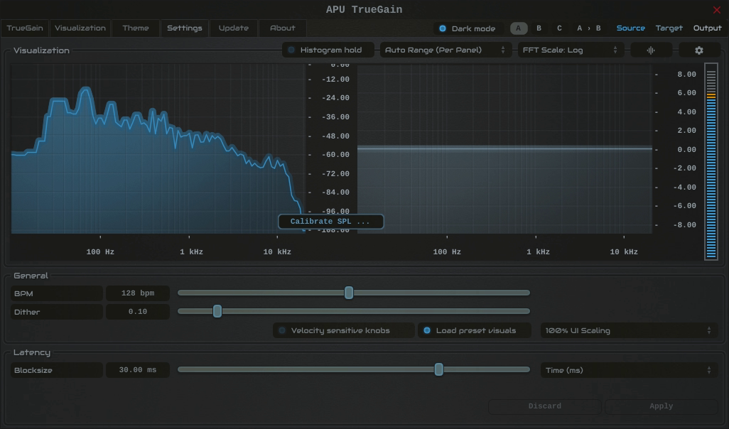
The settings tab contains various additional parameters. These parameters are broken down between General and Latency parameters. Since Latency parameters impact delay compensation, changes to these parameters are deferred until you click the Apply button. It is generally not advisable to automate the parameters in the Latency section.
2.5.1. BPM
The bpm option allows you to set the BPM used by tempo-relative parameters.
2.5.2. Host BPM
The host bpm option enables usage of the host’s BPM for tempo-relative parameters. When disabled, the bpm parameter is used instead.
This parameter is not available (nor applicable) to the standalone application.
2.5.3. Dither
The dither parameter determines the strength of ballistics dithering. This parameter applies only to dithering ballistics type modes.
2.5.4. Velocity sensitive knobs
If enabled, this will turn on velocity-sensitive dragging, so that the faster the mouse moves, the bigger the movement to the knobs. This helps when making accurate small-scale adjustments.
This parameter is saved at user scope, so it will be remembered between sessions.
2.5.5. UI Scaling
The UI scaling option allows you to set the scaling of the user interface. This is useful for high-DPI displays, where the default scaling may be too small to read comfortably.
This parameter is saved at user scope, so it will be remembered between sessions.
2.5.6. Axis Scaling
The axis scaling option allows you to set the scaling of the axis ticks, labels and text bubbles. This is useful for high-DPI displays, where the default scaling may be too small to read comfortably.
This parameter is saved at user scope, so it will be remembered between sessions.
2.5.7. Dark mode
The dark mode toggle enables/disables dark mode. When enabled, theme colors have their brightness inverted.
2.5.8. Gain change write
The gain change write mode controls how the plug-in publishes the latest signed gain change to the host as an automatable parameter. This can be useful for recording the plug-in’s gain changes directly to an automation lane when supported by the DAW.
Disabled turns gain change write off.
Native uses the format-native write path when available. For non-VST3 plug-ins, Native falls back to the same behavior as Compatibility.
Compatibility uses the generic host-notify write path, which may work in more places but is less elegant than Native when the host supports the native path.
Host support for plug-in generated automation varies. When supported, put the host into Write or Touch mode and record the Gain Change Write parameter.
Gain change write is output-only. The recorded automation lane is not read back into the plug-in’s processing.
2.5.9. Blocksize
The block size parameter determines the time frequency of FFT filtering. Generally speaking, lower block sizes will give more accurate results. However, lower block sizes also require more CPU resources, so it is necessary to find a balance. You can squeeze improved quality and/or performance by tuning this setting based on your available CPU resources.
BPM units for block size are evaluated once at the time you press Apply.
2.5.10. Look-ahead budget
The look-ahead budget parameter determines the latency budget which is available for the look-ahead parameter. Once you have configured a look-ahead budget, you can adjust the look-ahead parameter in real-time within this range without introducing artifacts.
2.5.11. Delay compensation
The delay compensation parameter determines whether or not the plug-in will report latency to the host. Delay compensation is used by hosts to keep audio synchronized across channels.
The delay compensation option is not available (nor applicable) to the standalone application.
2.6. Update
The update tab allows you to check for the latest product versions. Just click “Check for updates” to see the latest version numbers. If you’re not running the latest version, you can click “Download” to open the download page in your default browser.
2.7. About
The about tab contains basic information about the plug-in. This is also where you can activate or deactivate your product keys and check license status.
3. Worked examples
See True gain mode and Adaptive SPL for the related controls.
These examples separate the contour adjustment from scalar gain, the level offset applied equally at all frequencies. EQ can change a signal’s measured LUFS, RMS, and peak level even when scalar gain is 0 dB.
Use the same SPL contour model and set Output type to Normal when comparing these settings. Stop calibration playback and allow the attack/release response to settle. The True gain limits must allow the stated adjustments. The example contour levels do not require raising your speaker or headphone volume to 83 dB SPL.
Output gain is available through your DAW’s plug-in parameter or automation list; TrueGain’s custom editor has no dedicated Output gain control. Where an example needs an output trim, you can use this parameter or a separate downstream gain stage.
A 75-to-83 contour with 0 dB scalar gain
To apply the contour difference from 75 to 83 while keeping scalar gain at 0 dB, use:
- True gain mode: Translation Check.
- Reference SPL: 75 dB SPL.
- Target SPL: 83 dB SPL.
- Output gain: 0 dB.
- Adaptive SPL: Off for this fixed example.
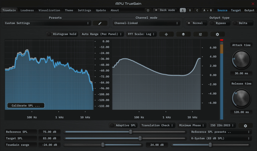
Shown with ISO 226:2023 and Minimum Phase.
An equivalent Compensated Gain Control setup uses Reference SPL = 83, True gain = -8 dB, and Output gain = +8 dB. Its contour starts at 83 + (-8) = 75 and ends at 83; its scalar gain is -8 + 8 = 0 dB.
Built-in Output gain can provide the +8 dB trim instead of a separate downstream gain stage. This equivalence assumes no additional level processing between the compared gain stages. Translation Check keeps Reference SPL at the calibrated 75 dB baseline in this example; the alternate CGC setup uses 83 as its calculation anchor.
A 65-to-83 contour with -10 dB scalar gain
For the quieter comparison, use Compensated Gain Control with Reference SPL = 83, True gain = -18 dB, Output gain = +8 dB, and Adaptive SPL off.
- Contour:
83 + (-18) = 65, through to 83. - Scalar gain:
-18 + 8 = -10 dB.
Translation Check with Reference SPL = 65, Target SPL = 83, and Output gain = -10 dB produces the same contour and scalar gain. Here 65 specifies the desired contour start; the -10 dB output trim is a separate level adjustment. These settings illustrate the filter calculation, rather than measuring your playback SPL.
When the input is 6 dB louder
Select Speakers: Pink Noise (Band-Limited), Momentary loudness, and K-weighting. Its stored calibration baseline is -22.22 LUFS. An input reading of -16.22 LUFS gives a +6 dB Reference Offset. Enable Adaptive SPL and set Reference Offset limits to allow +6 dB, such as -12 to +12 dB.
| Mode and settings | At the calibration baseline | With input +6 dB |
|---|---|---|
| CGC: Reference 83, True gain -8, Output gain +8 | Contour 75 to 83; scalar gain 0 dB | Contour 81 to 89; scalar gain 0 dB |
| Translation Check: Reference 75, Target 83, Output gain 0 | Contour 75 to 83; scalar gain 0 dB | Contour 81 to 89; scalar gain 0 dB |
| Compensated AGC: Reference 75, Target 83, Output gain 0 | Contour 75 to 83; scalar gain +8 dB | Contour 81 to 83; scalar gain +2 dB |
In CGC, Adaptive SPL updates the contour reference while True gain continues to set the gain adjustment. In Translation Check, it adds the same offset to both contour references: the Target SPL control stays at 83, but the effective target becomes 83 + 6 = 89. Neither mode automatically removes the input’s 6 dB increase.
Compensated AGC keeps its target at 83. The estimated input level rises from 75 to 81, so the required scalar gain falls from +8 to +2 dB. Attack/release smoothing controls how quickly this happens; the EQ change can also affect measured output loudness.
If the maximum Reference Offset is +3 dB, the same +6 dB input difference is capped at +3. The CGC and Translation Check examples then use contours from 78 to 86. AGC uses 78 to 83 and requests +5 dB scalar gain. Reference Offset limits and True gain limits have separate effects; a gain limit can prevent AGC from completing the requested correction.
Target SPL and a LUFS target
Target SPL is based on the selected calibration signal, input measurement, and calibrated playback level. It is not a fixed LUFS delivery target. A playback service’s normalization target also does not establish the level reaching TrueGain; use the input meter and its selected measurement window.
For a delivery requirement such as -14 LUFS integrated, measure the processed track’s integrated loudness. A Target SPL setting alone cannot guarantee that result.
4. Standalone CLI
APU TrueGain’s standalone application exposes a small user-facing command-line interface for loading, saving, and resetting standalone preset files. This section documents the supported options only.
Supported options:
--helpprints the supported standalone CLI options and exits.--resetParamsresets parameters after the standalone app loads its remembered state.--loadPreset="<path>"loads a preset file before the window is shown.--savePreset="<path>"writes the resulting preset file and exits without opening the user interface.
Processing order:
- The standalone app first loads its normal remembered standalone state.
- If
--resetParamsis present, a full parameter reset is applied. - If
--loadPresetis present, that preset file is loaded next. - If
--savePresetis present, the resulting state is written to disk and the app exits immediately.
Examples:
<standalone-app> --help<standalone-app> --savePreset="C:\Temp\truegain-startup.preset"<standalone-app> --resetParams --savePreset="C:\Temp\truegain-reset.preset"<standalone-app> --loadPreset="/tmp/truegain-session.preset"<standalone-app> --loadPreset="/tmp/truegain-session.preset" --savePreset="/tmp/truegain-copy.preset"
Compatibility:
--loadPresetand--savePresetuse the same file format as the standalone app’s standard JUCE options-button commands,Save current state...andLoad a saved state....- These file-based presets store the full standalone processor state. They are different from the in-app presets combo-box, which loads the product’s built-in preset entries and user preset-list selections.
5. Glossary
This section defines some of the concepts used within the software.
5.1. Range sliders
Range sliders are used throughout the plug-in in order to specify the upper and lower boundaries of a range. These ranges can be controlled via mouse in various ways.
- Click and drag the lower thumb to adjust the minimum value.
- Click and drag the upper thumb to adjust the maximum value.
- Click and drag the region between slider thumbs to move both values. This allows you to adjust the average loudness without expanding/contracting the dynamic range.
- Ctrl + click and drag the region between slider thumbs to expand/contract range without changing the average (center) value. Drag the mouse up and down, left and right are ignored.
- Shift + click and drag the region between slider thumbs to combine both. Drag the mouse up and down to expand/contract range. Drag the mouse left and right to move both values.
5.2. Histogram
One of the primary views into your audio that this software provides is a real-time histogram. Histograms in general provide a quick and intuitive way to understand the relative frequency of different measurements. This is very useful when judging the overall dynamic range of the audio. The histogram provided by this software is capable of changing history length, bucket size and size continuously.
5.3. Source
The term “source” is used throughout the plug-in to identify the plug-in’s input source signal. This signal is represented in the user interface by the current theme’s source color.
5.4. Target
The term “target” is used throughout the plug-in to identify the configured target range loudness. This signal is represented in the user interface by the current theme’s target color.
5.5. Output
The term “output” is used throughout the plug-in to identify the output type signal. This signal is represented in the user interface by the current theme’s output color.
6. Credits
This software was developed by APU Software, LLC and is available as VST (windows x64/x86, macOS universal), Audio Unit (macOS universal), Pro Tools AAX (windows x64, macOS universal), or Standalone Application (windows x64/x86, macOS universal). The software libraries below are utilized for portions of the software:
- JUCE (cross-platform audio and user interface framework)
- Boost (header-only algorithms)
- melatonin_blur (blur effects)
- PFFFT (FFT library)
Demo video song credits:


6.1. MIT License (libebur128)
Copyright (c) 2011 Jan Kokemüller
Permission is hereby granted, free of charge, to any person obtaining a copy
of this software and associated documentation files (the "Software"), to deal
in the Software without restriction, including without limitation the rights
to use, copy, modify, merge, publish, distribute, sublicense, and/or sell
copies of the Software, and to permit persons to whom the Software is
furnished to do so, subject to the following conditions:

The above copyright notice and this permission notice shall be included in
all copies or substantial portions of the Software.

THE SOFTWARE IS PROVIDED "AS IS", WITHOUT WARRANTY OF ANY KIND, EXPRESS OR
IMPLIED, INCLUDING BUT NOT LIMITED TO THE WARRANTIES OF MERCHANTABILITY,
FITNESS FOR A PARTICULAR PURPOSE AND NONINFRINGEMENT. IN NO EVENT SHALL THE
AUTHORS OR COPYRIGHT HOLDERS BE LIABLE FOR ANY CLAIM, DAMAGES OR OTHER
LIABILITY, WHETHER IN AN ACTION OF CONTRACT, TORT OR OTHERWISE, ARISING FROM,
OUT OF OR IN CONNECTION WITH THE SOFTWARE OR THE USE OR OTHER DEALINGS IN
THE SOFTWARE.
6.2. MIT License (melatonin_blur)
Copyright (c) 2023 Sudara Williams
Permission is hereby granted, free of charge, to any person obtaining a copy
of this software and associated documentation files (the "Software"), to deal
in the Software without restriction, including without limitation the rights
to use, copy, modify, merge, publish, distribute, sublicense, and/or sell
copies of the Software, and to permit persons to whom the Software is
furnished to do so, subject to the following conditions:

The above copyright notice and this permission notice shall be included in all
copies or substantial portions of the Software.

THE SOFTWARE IS PROVIDED "AS IS", WITHOUT WARRANTY OF ANY KIND, EXPRESS OR
IMPLIED, INCLUDING BUT NOT LIMITED TO THE WARRANTIES OF MERCHANTABILITY,
FITNESS FOR A PARTICULAR PURPOSE AND NONINFRINGEMENT. IN NO EVENT SHALL THE
AUTHORS OR COPYRIGHT HOLDERS BE LIABLE FOR ANY CLAIM, DAMAGES OR OTHER
LIABILITY, WHETHER IN AN ACTION OF CONTRACT, TORT OR OTHERWISE, ARISING FROM,
OUT OF OR IN CONNECTION WITH THE SOFTWARE OR THE USE OR OTHER DEALINGS IN THE
SOFTWARE.
6.3. FFTPACK License (pffft)
Copyright (c) 2013  Julien Pommier ( pommier@modartt.com )
Based on original fortran 77 code from FFTPACKv4 from NETLIB,
authored by Dr Paul Swarztrauber of NCAR, in 1985.
As confirmed by the NCAR fftpack software curators, the following
FFTPACKv5 license applies to FFTPACKv4 sources. My changes are
released under the same terms.
FFTPACK license:
http://www.cisl.ucar.edu/css/software/fftpack5/ftpk.html
Copyright (c) 2004 the University Corporation for Atmospheric
Research ("UCAR"). All rights reserved. Developed by NCAR's
Computational and Information Systems Laboratory, UCAR,
www.cisl.ucar.edu.
Redistribution and use of the Software in source and binary forms,
with or without modification, is permitted provided that the
following conditions are met:
- Neither the names of NCAR's Computational and Information Systems
Laboratory, the University Corporation for Atmospheric Research,
nor the names of its sponsors or contributors may be used to
endorse or promote products derived from this Software without
specific prior written permission.
- Redistributions of source code must retain the above copyright
notices, this list of conditions, and the disclaimer below.
- Redistributions in binary form must reproduce the above copyright
notice, this list of conditions, and the disclaimer below in the
documentation and/or other materials provided with the
distribution.
THIS SOFTWARE IS PROVIDED "AS IS", WITHOUT WARRANTY OF ANY KIND,
EXPRESS OR IMPLIED, INCLUDING, BUT NOT LIMITED TO THE WARRANTIES OF
MERCHANTABILITY, FITNESS FOR A PARTICULAR PURPOSE AND
NONINFRINGEMENT. IN NO EVENT SHALL THE CONTRIBUTORS OR COPYRIGHT
HOLDERS BE LIABLE FOR ANY CLAIM, INDIRECT, INCIDENTAL, SPECIAL,
EXEMPLARY, OR CONSEQUENTIAL DAMAGES OR OTHER LIABILITY, WHETHER IN AN
ACTION OF CONTRACT, TORT OR OTHERWISE, ARISING FROM, OUT OF OR IN
CONNECTION WITH THE SOFTWARE OR THE USE OR OTHER DEALINGS WITH THE
SOFTWARE.